 |
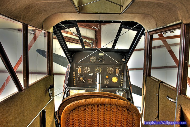
| Starting with a beautiful original panel like this, one could hardly agree to add or take away anything. |
As we attack this challenge for a 1929 Curtiss Robin, I will be posting photos and looking for suggestions and comments from our readers. In this, PART 1, segment, we'll look at the battery installation.
Weight and CG are primary factors here, as well as structural strength. We'll be upgrading from a hand-crank inertia starter to an electric starter for this Curtiss R-600 Challenger engine at the same time. As a result, we'll be adding approximately 14 pounds forward in the engine section of the airplane before we even consider adding a battery. There are just not many choices for starters on the R-600 beyond the Big and Heavy old Eclipse starters. We are going to need a battery with some gusto behind it to supply the cranking amperage necessary to flip over the heavy double-throw crankshaft and heavy ground adjustable propeller on this engine.
We're pleased to know that such a battery exists in a small package. The Odyssey SBS-J16 has become one of the most popular batteries for use in light-weight airplanes. This is a dry-cell battery about half the size and weight (13.5 pounds) of a conventional 12 volt aircraft battery. Still, the physical properties of the gel-acid design of this battery lends itself to a high rating for cold cranking amperage and long ampere-hour charge retention properties.
 |
| Odyssey SBS-J16 Battery is FAA-PMA approved on Piper PA18 and other aircraft. |
Now, considering where to mount this thing is another challenge. As stated we don't want to add any more weight forward in the engine compartment if we can help it. But then if we put it too far aft, we'll require some rather long runs of heavy copper wire cables that can be unsightly themselves. With little room underneath the floor and no hidden compartments to consider, we are left with no other choice than to place the battery within the cabin most likely in full view of curious admirers of the airplane. An ideal CG location might have been just behind the pilot's seat on the floor in full view of anyone climbing or peering in through the rear cabin entry door. Another location not as favorable for the CG, but less conspicuous to the casual observer would be on the aft side of the firewall below and head of the rudder pedals. This model C-1 Robin has room in this location and the width of the battery is just right to allow (not a lot, but ample) clearance between the rudder pedal's range of motion.
I started looking at photos of other Curtiss Robins to see if we could find out how some other battery installations have been approved. I found one with the battery mounted on the floor just ahead of the pitch-trim lever. I felt that this location was not only a bit unsightly, but there were also considerations for a fuel line in the area which might require re-routing.
 |
| This battery location seems in appropriate. |
I ran across a couple of photos of model B Robins and learned something I had never noticed. It seems the OX-5 installations on the model B required a sheet metal box protrusion aftward from the rear face of the firewall.I am not sure what component of the OX engine would have required this space accommodation, but the size and location of this box was similar to the battery box installation I was considering.


So this settled it. I decided this is the best location for the battery. Not perfect from a CG standpoint, but I feel it is a manageable point. This will bear out later when we do the final weighing of the assembled aircraft. If necessary, we may need to consider ballast in the tail but the decision is made. Cosmetically, it will blend in. Clearance-wise, there are no issues. Structurally, we will be able to take advantage of a steel tube brace that runs right across the front face of the firewall at this location to provide forward load bearing. And the firewall itself will be used along with a newly fabricated sheet metal doubler to provide downward and side loading support.
Though not completely hidden from sight, the battery box holds similar appearance to that of the OX-5 firewall box (whatever it is for). One of the best aspects of this location is that the battery will be rather easily accessible for maintenance. Since the firewall doubler is located on the front face of the firewall behind the oil tank, it will be impossible to reach it from the engine side. So, I attached floating nut-plates to the doubler. The nutplates allow the mechanic to remove and replace the battery working the six bolts only from the cabin side with a simple ratchet driver. It is not necessary to hold a wrench on the engine side.
 |
| Sheet metal doubler on the forward face of the firewall. |
 |
| Battery Box final installation. |
 |
| Rudder pedal clearance, and accessibility. |

