Thursday, July 10, 2014

85 Years Ago This Month - A whole lot of Flying Going on!!!

This Week in Aviation History -  Way back in 1929, the 2nd week of July marked an exciting time in the History of Aviation for Air-to-Air re-fueling and Atlantic Ocean crossings.  It must have been the exceptional weather and man's quest for notoriety that led to the following events.  Note the dates... Many of these interesting flights overlapped each other as newspapers across the world followed the action.


JUNE 30 thru JULY 6, 1929: NEW IN-FLIGHT RE-FUELED ENDURANCE RECORD
7 DAYS, 6 HOURS, 00 MINUTES, 00 SEC.
Roy Mitchell and Byron K. Newcomb flying a Stinson Detroiter
Cleveland Ohio.
Photo: Critical Past -
 
JULY 2 - 12, 1929: NEW IN-FLIGHT RE-FUELED ENDURANCE RECORD
10 DAYS, 6 HOURS, 43 MINUTES, 32 SEC.
Loren W. Mendell and Roland B. Reinhart flying a Buhl CA-5A Airsedan nicknamed "Angelino"
Los Angeles, California
Photo: DMAIRFIELD.COM - Gerow Collection


Photo FAI.org


JULY 13 - 30, 1929:   NEW IN-FLIGHT RE-FUELED ENDURANCE RECORD
17 DAYS, 12 HOURS, 17 MINUTES, 00 SEC.
Dale Jackson and Forrest O'Brine flying a Curtiss Robin C-1 nicknamed the "St. Louis Robin" NR59H
Refueled by  Curtiss Robin NR81H: C. Ray Wassall and Percy V. Chaffee
Saint Louis Missouri


Photo: Bowden collection of News Clippings


JULY 13 1929 ATLANTIC OCEAN CROSSING ATTEMPT - 1st. West to East
Dieudonne Costes and Maurice Bellonte Flying a French Breguet 19 nicknamed "?"
Returned after 17 hours to LeBorget Airport after facing bad weather
Paris France

Photo: Acepilots.com


Photo: Wikipedia

JULY 17 - 22, 1929 RE-FUELED ENDURANCE RECORD ATTEMPT
4 DAYS, 21 HOURS, 20 MINUTES, 00 SEC
Joseph A. Hammer and W. Gentry Shelton flying a Curtiss Robin C-1 nicknamed " The Missouri Robin" NR78H
Refueled by Curtiss Robin C-1 NR82H: Eyer L Sloniger and Frank Buchanan
Saint Louis, Missouri


JULY 18 - 27, 1929 RE-FUELED ENDURANCE RECORD ATTEMPT
9 DAYS, 7 HOURS, 12 MINUTES, 00 SEC
Joe Glass and Glenn L. Loomis flying a Stinson Detroiter nicknamed"Billion Dollar City"
Houston, Texas


JULY 23 - 29, 1929 RE-FUELED ENDURANCE RECORD ATTEMPT
6 DAYS, 25 HOURS, 45 MINUTES, 00 SEC.
Owen T. Haugland and P. J. Crichton flying a Cessna nicknamed "The Minnesota"
Plane crashed, killing Crichton, and injuring Haugland
Minneapolis, Minnesota

Photo: Hannepin County Library
Photo: Googlenews.com

JULY 27, 1929 ATLANTIC OCEAN CROSSING SUCCESS
Graf Zeppelin left Friedrichshafen on July 27, 1929 and crossed the Atlantic to Lakehurst, New Jersey,


Wednesday, July 9, 2014

Modern updates to an Historic Aircraft - Pt. 2

We have been following the team at Certified Aeronautical Products, LLC who is busy incorporating an electrical system to an Historic Curtiss Robin aircraft which previously was non-electrical.  For the most part, this particular airplane retains the mystique of its original instrument panel configuration.  Their challenge is to implement modern  electrical components and avionics without significant changes to the look of the airplane. We previously looked at the battery installation in Part 1.  So now, we will watch as this airplane is permanently altered with a master switch, master relay, starter relay, power buss, ammeter/voltmeter, and some important indicator lights.

CAP Technician making a permanent change to this Robin's sub-panel.
 The following standards were the rule in this job.
1) Safety and regulatory compliance are the first priorities (in that order).
2) Whenever possible, avoid alterations that change the panel and interior furnishings. (i.e. Don't drill a hole unless there is no other alternative!)
3) If altering anything, try to do so with minimal changes and try to do so in a way that retains the original "look" and feel of the airplane.

The next image shows the original instrument panel prior to alterations.  The following images show the added components.

Notice that there is a toggle switch visible on the lower sub panel in the "before" modification photo.  As it turns out, this switch (labeled "Navigation Lights") was not connected at all.  The aircraft has no navigation lights.  Aparently, this switch was added sometime in the airplane's history.  So, we decided to utilize this location for our "master" switch. This will be discussed in further detail later on.

The airplane will utilize an alternator to charge the battery during operations. The customer also requested two power receptacles (cigarrette lighter sockets).  These will be used for portable electronic devices such as a GPS or to charge cellular phones, tablets, or laptops.  Therefore, it was necessary to install a "power buss" with circuit breakers for the alternator, "power socket A" and "power socket B".

New power buss with room for expansion.
 
Power buss under the sub panel.
Mounting for the power buss was accomplished flush screws hidden behind the aircraft data plate.  The assembly is positioned with room for labeling just under the data plate.  The circuit breakers are easily seen if "popped" and convenient to the pilot for re-set. Also visible in the above photo is the combination ammeter/voltmeter instrument.  The location was chosen as the instrument may be hidden during static display by reinstalling the plastic pouch which holds the original registration certificate.  Behind the ammeter and the left rudder bar is the electrical "shunt" which is a necessary part of the ammeter/voltmeter installation.

Normal view of the instrument panel (after mods). 
Note in the "after" photo there are two indicator lights added.  One is just to the left of the hand crank for magneto booster.  This light indicates when the master switch is "on".  The other is above the starter tee-handle control to indicate when the starter is engaged.  The power circuit breakers are barely visible below the data plate.  And the new ammeter/voltmeter has been added to the lower "sub-panel".


  The last photo shows the forward side of the firewall where the electrical equipment and wiring are neatly installed.  Note the master solenoid is mounted at the right and the starter solenoid at the left.  Most of this will be hidden behind the oil tank which was removed at the time of this photo.  One more change will be necessary.  That is to change up the orientation and routing of the fuel primer and primer lines (at mid left)  for better separation from the electrical wiring. Look for further discussion of the starter switch installation (mid right in photo) in the next installment of this series.

Tuesday, June 3, 2014

Modern updates to an Historic Aircraft - Pt. 1

Here's the challenge... Take a pristine all-original 1929 aircraft and update it with modern avionics, without degrading its historical integrity.  This is a dilemma that many vintage airplane restorers face. Sometimes you just have to face it head-on and move toward improved safety and operational feasibility.  But there are ways one can do so without significant degradation of the pleasing cosmetic value of the antique specimen.
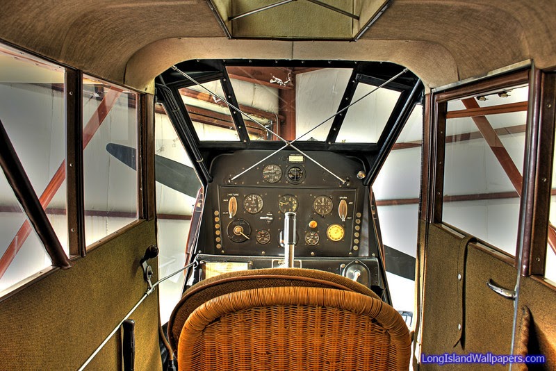
Starting with a beautiful original panel like this, one could hardly agree to add or take away anything.

As we attack this challenge for a 1929 Curtiss Robin, I will be posting photos and looking for suggestions and comments from our readers.  In this, PART 1, segment, we'll look at the battery installation.

Weight and CG are primary factors here, as well as structural strength.  We'll be upgrading from a hand-crank inertia starter to an electric starter for this Curtiss R-600 Challenger engine at the same time.  As a result, we'll be adding approximately 14 pounds forward in the engine section of the airplane before we even consider adding a battery.  There are just not many choices for starters on the R-600 beyond the Big and Heavy old Eclipse starters. We are going to need a battery with some gusto behind it to supply the cranking amperage necessary to flip over the heavy double-throw crankshaft and heavy ground adjustable propeller on this engine.

We're pleased to know that such a battery exists in a small package.  The Odyssey SBS-J16 has become one of the most popular batteries for use in light-weight airplanes.  This is a dry-cell battery about half the size and weight (13.5 pounds) of a conventional 12 volt aircraft battery.  Still, the physical properties of the gel-acid design of this battery lends itself to a high rating for cold cranking amperage and long ampere-hour charge retention properties.

Odyssey SBS-J16 Battery is FAA-PMA approved on Piper PA18 and other aircraft.


Now, considering where to mount this thing is another challenge.  As stated we don't want to add any more weight forward in the engine compartment if we can help it. But then if we put it too far aft, we'll require some rather long runs of heavy copper wire cables that can be unsightly themselves.  With little room underneath the floor and no hidden compartments to consider, we are left with no other choice than to place the battery within the cabin most likely in full view of curious admirers of the airplane.  An ideal CG location might have been just behind the pilot's seat on the floor in full view of anyone climbing or peering in through the rear cabin entry door.  Another location not as favorable for the CG, but less conspicuous to the casual observer would be on the aft side of the firewall below and head of the rudder pedals.  This model C-1 Robin has room in this location and the width of the battery is just right to allow  (not a lot, but ample) clearance between the rudder pedal's range of motion.

I started looking at photos of other Curtiss Robins to see if we could find out how some other battery installations have been approved.  I found one with the battery mounted on the floor just ahead of the pitch-trim lever.  I felt that this location was not only a bit unsightly, but there were also considerations for a fuel line in the area which might require re-routing.

This battery location seems in appropriate.


I ran across a couple of photos of model B Robins and learned something I had never noticed.  It seems the OX-5 installations on the model B required a sheet metal box protrusion aftward from the rear face of the firewall.I am not sure what component of the OX engine would have required this space accommodation, but the size and location of this box was similar to the battery box installation I was considering.


So this settled it.  I decided this is the best location for the battery.  Not perfect from a CG standpoint, but I feel it is a manageable point.  This will bear out later when we do the final weighing of the assembled aircraft.  If necessary, we may need to consider ballast in the tail but the decision is made.  Cosmetically, it will blend in.  Clearance-wise, there are no issues.  Structurally, we will be able to take advantage of a steel tube brace that runs right across the front face of the firewall at this location to provide forward load bearing.  And the firewall itself will be used along with a newly fabricated sheet metal doubler to provide downward and side loading support.

Though not completely hidden from sight, the battery box holds similar appearance to that of the OX-5 firewall box (whatever it is for).  One of the best aspects of this location is that the battery will be rather easily accessible for maintenance Since the firewall doubler is located on the front face of the firewall behind the oil tank, it will be impossible to reach it from the engine side. So, I attached floating nut-plates to the doubler. The nutplates allow the mechanic to remove and replace the battery working the six bolts only from the cabin side with a simple ratchet driver. It is not necessary to hold a wrench on the engine side.


Sheet metal doubler on the forward face of the firewall.

Battery Box final installation.

Rudder pedal clearance, and accessibility.


Barnstmr's Random Slideshow

Blog Followers